 Thai Baht Converter
เครื่องมือวัดอุตสาหกรรม l Measuring Instruments [10184]
คุณสมบัติการใช้งานเครื่องมือวัด l Featured Products [870]
| รหัสสินค้า | SKU-00802 |
| หมวดหมู่ | เครื่องวัดและทดสอบไฟฟ้า(Electrical test and Measurement) |
| ราคาปกติ | |
| ลดเหลือ | 0.00 บาท |
| สถานะสินค้า | Pre-Order |
| สภาพ | สินค้าใหม่ |
| ลงสินค้า | 14 พ.ย. 2561 |
| อัพเดทล่าสุด | 11 ก.ค. 2568 |
| คงเหลือ | 1 ชิ้น |
| จำนวน | ชิ้น |


 |

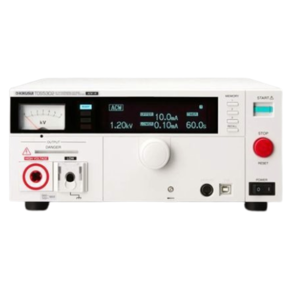
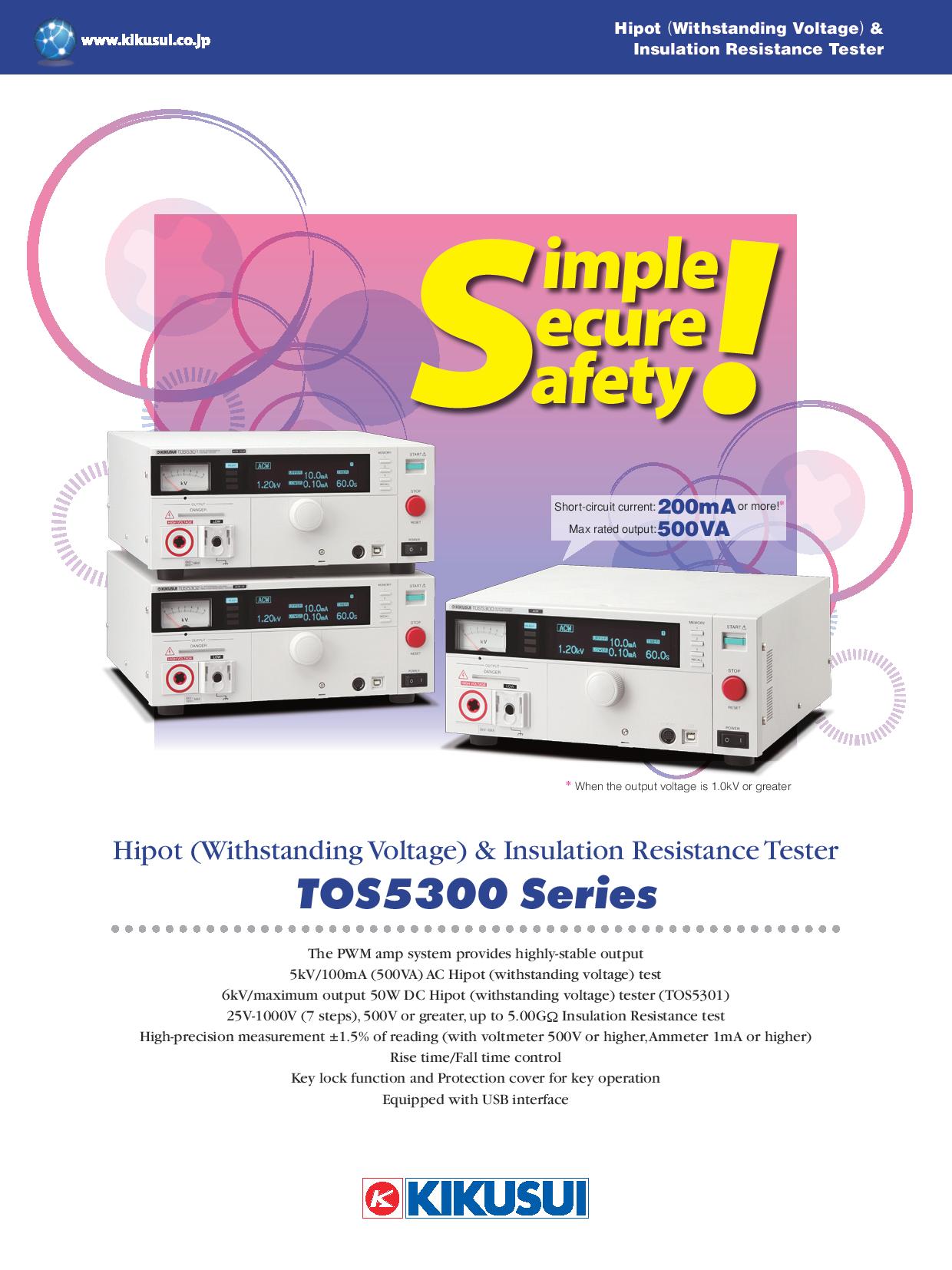
The TOS5300 series is a tester for withstanding voltage test and insulation resistance test among the four tests required to ensure the safety of electrical products. We can perform withstand voltage tests/insulation resistance tests for electronic devices and electronic components based on the requirements of the safety standards of each country, such as IEC, EN, UL, VDE, and JIS, as well as the requirements of the Electrical Appliance and Material Safety Law. In addition, the stability of the test voltage is improved by adopting a newly developed switching amplifier. Since the output voltage can be kept constant even if the AC line voltage or frequency changes, stable testing can be performed even in areas where the power supply environment is unstable.


|
name |
Withstanding Voltage Tester TOS5302 |
||||||||||||||||||||||
|
Basic function |
AC withstanding voltage/insulation resistance tester (ACW/IR) |
||||||||||||||||||||||
|
■ Withstand voltage test section |
|||||||||||||||||||||||
|
AC |
output |
range |
0.05kV to 5.00kV |
||||||||||||||||||||
|
Setting accuracy |
± (2 % of set + 20 V) [at no load] |
||||||||||||||||||||||
|
Setting range |
0.00kV to 5.50kV |
||||||||||||||||||||||
|
Setting resolution |
10V STEP |
||||||||||||||||||||||
|
Maximum rated output |
500VA (5kV/100mA) |
||||||||||||||||||||||
|
Maximum rated voltage |
5 kV |
||||||||||||||||||||||
|
Maximum rated current |
100 mA [output voltage 0.5 kV or more] |
||||||||||||||||||||||
|
transformer capacity |
500 VA |
||||||||||||||||||||||
|
Output voltage waveform |
sine wave |
||||||||||||||||||||||
|
Output voltage waveform distortion factor |
Output voltage 0.5 kV or more: 3 % or less (at no load and pure resistance load) |
||||||||||||||||||||||
|
frequency |
50Hz / 60Hz |
||||||||||||||||||||||
|
Frequency accuracy |
±0.5 % (except during voltage rise) |
||||||||||||||||||||||
|
voltage regulation |
10% or less (maximum rated load → no load) |
||||||||||||||||||||||
|
Input voltage fluctuation |
± 0.3 % (at 5 kV no load, supply voltage 90 V to 250 V) |
||||||||||||||||||||||
|
Short-circuit current |
200 mA or more (output voltage 1.0 kV or more) |
||||||||||||||||||||||
|
Output method |
PWM switching method |
||||||||||||||||||||||
|
DC output section |
× (no function) |
||||||||||||||||||||||
|
Start Voltage |
The voltage at the start of the withstanding voltage test can be set to 50% of the set voltage |
||||||||||||||||||||||
|
Limit Voltage |
Upper limit reference value for test voltage setting can be set |
||||||||||||||||||||||
|
Output voltage monitoring function |
When the output voltage exceeds the set value (±350V), the output is cut off for protection. |
||||||||||||||||||||||
|
voltmeter |
analog |
scale |
6kV AC/DC fs |
||||||||||||||||||||
|
Accuracy |
±5% fs |
||||||||||||||||||||||
|
instructions |
Average response/rms scale |
||||||||||||||||||||||
|
Digital |
Measurement range |
0.000kV to 6.500kV AC/DC |
|||||||||||||||||||||
|
display |
□ . □□□ kV |
||||||||||||||||||||||
|
Accuracy |
V < 500V: ± (1.5% of rdng + 20V) |
||||||||||||||||||||||
|
response |
True rms/average response rms display switchable |
||||||||||||||||||||||
|
Hold |
Holds the measured voltage value at the end of the test during the PASS/FAIL period. |
||||||||||||||||||||||
|
Ammeter |
Digital |
Measurement range |
AC: 0.00mA to 110mA |
||||||||||||||||||||
|
display |
i = measured current |
||||||||||||||||||||||
|
Accuracy |
1.00 mA ≤ i: ± (1.5 % of rdng) |
||||||||||||||||||||||
|
response |
True rms/average response rms display switchable |
||||||||||||||||||||||
|
Hold |
Holds the measured voltage value at the end of the test during the PASS period |
||||||||||||||||||||||
|
Judgment |
Judgment method/judgment action |
· PASS signal is output continuously until STOP is input when PASS HOLD is set · UPPER FAIL and LOWER FAIL signals are output continuously until STOP is input · Adjustable FAIL or PASS buzzer volume · The buzzer sound at PASS judgment is fixed at 0.2 s, and the buzzer is turned off at 0.2 s even during PASS HOLD. |
|||||||||||||||||||||
|
Upper limit reference value setting |
AC: 0.01mA to 110mA |
||||||||||||||||||||||
|
Lower reference value setting |
AC: 0.01mA to 110mA/OFF |
||||||||||||||||||||||
|
Judgment accuracy |
1.00 mA ≤ i: ± (1.5 % of set) |
||||||||||||||||||||||
|
Current detection method |
Calculate the true rms value of the current or the average value and compare it with the reference value |
||||||||||||||||||||||
|
Proofreading |
Calibrated at the rms value of a sine wave with a purely resistive load |
||||||||||||||||||||||
|
time |
Voltage Rise |
range |
0.1s to 10.0s |
||||||||||||||||||||
|
Setting resolution |
0.1s |
||||||||||||||||||||||
|
Voltage fall time |
0.1 s / OFF (valid only for PASS judgment) |
||||||||||||||||||||||
|
Test |
range |
0.1 s to 999 s test time off (TIMER OFF) function available |
|||||||||||||||||||||
|
Setting resolution |
0.1s to 99.9s: 0.1s / 100s to 999s: 1s |
||||||||||||||||||||||
|
Accuracy |
± (100 ppm + 20 ms) |
||||||||||||||||||||||
|
■ Insulation resistance tester section |
|||||||||||||||||||||||
|
Output part |
output voltage |
setting |
25 V, 50 V, 100 V, 125 V, 250 V, 500 V, 1000 V DC/Negative polarity |
||||||||||||||||||||
|
Setting accuracy |
-0%, +5% |
||||||||||||||||||||||
|
Maximum rated load |
1W (-1000V DC/1mA) |
||||||||||||||||||||||
|
Maximum rated current |
1mA |
||||||||||||||||||||||
|
ripple |
1000V |
2 Vp-p or less |
|||||||||||||||||||||
|
Maximum rated load |
10 Vp-p or less |
||||||||||||||||||||||
|
voltage regulation |
1 % or less (maximum rated load → no load) |
||||||||||||||||||||||
|
Short-circuit current |
12 mA or less |
||||||||||||||||||||||
|
discharge function |
Forced discharge at the end of the test (discharge resistance approx. 25 kΩ) |
||||||||||||||||||||||
|
Limit Voltage |
25 V, 50 V, 100 V, 125 V, 250 V, 500 V, 1000 V |
||||||||||||||||||||||
|
Output voltage monitoring function |
Output is cut off when the output voltage exceeds ± (10% of set + 10 V) |
||||||||||||||||||||||
|
voltmeter |
analog |
scale |
6kV AC/DC fs |
||||||||||||||||||||
|
Accuracy |
±5% fs |
||||||||||||||||||||||
|
instructions |
Average response/rms scale |
||||||||||||||||||||||
|
Digital |
Measurement range |
0V to -1200V |
|||||||||||||||||||||
|
display |
|
||||||||||||||||||||||
|
Accuracy |
± (1% of rdng + 1V) |
||||||||||||||||||||||
|
resistance meter |
Measurement range |
25V |
30kΩ ≤ R ≤ 25 MΩ / ± (2% of rdng + 2 digits) |
||||||||||||||||||||
|
50V |
50kΩ ≤ R ≤ 50MΩ / ± (2% of rdng + 2 digits) |
||||||||||||||||||||||
|
100V |
100kΩ ≤ R ≤ 100MΩ / ± 2% of rdng |
||||||||||||||||||||||
|
125V |
125kΩ ≤ R ≤ 125MΩ / ± 2% of rdng |
||||||||||||||||||||||
|
250V |
250kΩ ≤ R ≤ 250MΩ / ± 2% of rdng |
||||||||||||||||||||||
|
500V |
500kΩ ≤ R ≤ 500MΩ / ± 2% of rdng |
||||||||||||||||||||||
|
1000V |
1 MΩ ≤ R < 1 GΩ / ± 2% of rdng |
||||||||||||||||||||||
|
display |
|
||||||||||||||||||||||
|
Hold function |
Holds the measured resistance value at the end of the test during the PASS period |
||||||||||||||||||||||
|
Current detection response speed (Response) |
Switch in 3 stages of FAST / MID / SLOW |
||||||||||||||||||||||
|
Judgment |
Judgment method/judgment action |
· PASS signal is output continuously until STOP is input when PASS HOLD is set. · UPPER FAIL and LOWER FAIL signals are output continuously until STOP is input · Adjustable FAIL or PASS buzzer volume · The buzzer sound at PASS judgment is fixed at 0.2 s, and the buzzer is turned off at 0.2 s even during PASS HOLD. |
|||||||||||||||||||||
|
Upper limit reference value setting range |
30kΩ to 5.00GΩ |
||||||||||||||||||||||
|
Lower reference value setting range |
30kΩ to 5.00GΩ |
||||||||||||||||||||||
|
Judgment accuracy UPPER |
Measurement accuracy +2 digit |
||||||||||||||||||||||
|
time |
Voltage rise time (Rise Time) |
10 ms (TYP value) |
|||||||||||||||||||||
|
Test |
range |
0.1 s to 999 s with test time off (TIMER OFF) function |
|||||||||||||||||||||
|
Setting resolution |
0.1s to 99.9s: 0.1s / 100s to 999s: 1s |
||||||||||||||||||||||
|
Accuracy |
± (100ppm + 20ms) |
||||||||||||||||||||||
|
■ Other functions/interfaces |
|||||||||||||||||||||||
|
Double Action |
The test starts only when the START switch is pressed within 0.5 seconds after the STOP switch is pressed and released. |
||||||||||||||||||||||
|
PASS judgment holding time (Pass Hold) |
Set time to hold PASS judgment: 50 ms/ 100 ms/ 200 ms/ 1 s/ 2 s/ 5 s/ HOLD |
||||||||||||||||||||||
|
Momentary function (Momentary) |
Run the test only while the START switch is pressed |
||||||||||||||||||||||
|
Fail mode function |
Disable FAIL or PROTECTION release by remote control stop signal |
||||||||||||||||||||||
|
Timer function (TIMER) |
End the test after the set time has passed |
||||||||||||||||||||||
|
Output voltage monitoring function (Volt Error) |
When the output voltage exceeds ±350 V of the set value, |
||||||||||||||||||||||
|
Memory |
Memorize up to 3 test conditions |
||||||||||||||||||||||
|
Key lock |
Disabling only setting/change operations from the panel |
||||||||||||||||||||||
|
protection |
In the following conditions, it shifts to the PROTECTION state, immediately cuts off the output, and stops the test. Show message on screen |
||||||||||||||||||||||
|
Interlock protection |
When an interlock signal input is detected |
||||||||||||||||||||||
|
Power supply protection |
When an abnormality in the power supply is detected |
||||||||||||||||||||||
|
Volt Error Protection |
When the output voltage is monitored and a voltage exceeding the specified range is detected, |
||||||||||||||||||||||
|
Over load protection |
If the power is set to the output limit power or more during the withstand voltage test, |
||||||||||||||||||||||
|
Over heat protection |
When the temperature inside the product rises abnormally |
||||||||||||||||||||||
|
Over Rating Protection |
When the output current exceeds the specified time during the withstand voltage test |
||||||||||||||||||||||
|
Calibration protection |
When the set calibration deadline has passed |
||||||||||||||||||||||
|
Remote protection |
When the disconnection of the REMOTE connector on the front panel is detected |
||||||||||||||||||||||
|
SIGNAL I/O Protection |
When the ENABLE signal of the SIGNAL I/O connector on the rear panel changes |
||||||||||||||||||||||
|
USB protection |
When the USB connector is pulled out during control with the USB interface |
||||||||||||||||||||||
|
system clock |
display |
Year/Month/Day Hour:Minute:Second |
|||||||||||||||||||||
|
Date and time of calibration |
Set during calibration service |
||||||||||||||||||||||
|
Calibration |
Set next calibration due date |
||||||||||||||||||||||
|
Calibration |
Set the operation when the set calibration deadline has passed. Displays a warning when the power is turned on |
||||||||||||||||||||||
|
interface |
USB |
USB Specification 2.0 |
|||||||||||||||||||||
|
REMOTE |
Front panel 9-pin MINI DIN connector Connects options |
||||||||||||||||||||||
|
SIGNAL I/O |
Rear panel D-sub 25 pin connector |
||||||||||||||||||||||
|
■ General specifications |
|||||||||||||||||||||||
|
display |
VFD: 256 x 64 dots + 4 STATUS display |
||||||||||||||||||||||
|
Backup battery life |
3 years (at 25°C) |
||||||||||||||||||||||
|
environment |
Installation location |
Indoors, up to 2000 m altitude |
|||||||||||||||||||||
|
Specification guarantee range temperature/humidity |
5°C to 35°C / 20% rh to 80% rh (non-condensing) |
||||||||||||||||||||||
|
Operating range temperature/humidity |
0°C to 40°C / 20% RH to 80% RH (non-condensing) |
||||||||||||||||||||||
|
Storage range temperature/humidity |
-20°C to 70°C/90% rh or less (no condensation) |
||||||||||||||||||||||
|
power supply |
Nominal voltage range (allowable voltage range) |
100Vac to 240Vac (90Vac to 250Vac) |
|||||||||||||||||||||
|
power consumption |
No load |
100 VA or less |
|||||||||||||||||||||
|
at rated load |
Up to 800VA |
||||||||||||||||||||||
|
Allowable frequency range |
47Hz to 63Hz |
||||||||||||||||||||||
|
Insulation resistance (between AC LINE and chassis) |
30 MΩ or more (500 Vdc) |
||||||||||||||||||||||
|
Dielectric strength (between AC LINE and chassis) |
1400 Vac, 2 seconds (100% test) / 1500 Vac, 1 minute (type test) |
||||||||||||||||||||||
|
ground continuity |
25Aac/0.1Ω or less |
||||||||||||||||||||||
|
safety |
Conforms to the requirements of the following directives and standards |
||||||||||||||||||||||
|
Electromagnetic Compatibility (EMC) |
Conforms to the requirements of the following directives and standards: |
||||||||||||||||||||||
|
External dimensions (maximum size) |
320 (330) W x 132 (150) H x 350 (420) D mm |
||||||||||||||||||||||
|
mass |
about 14kg |
||||||||||||||||||||||
|
accessories |
1 power cord |
||||||||||||||||||||||


") Realtools Asia(ศูนย์รวมเครื่องมือวัดและชุดทดสอบอุตสาหกรรม)
Realtools Asia(ศูนย์รวมเครื่องมือวัดและชุดทดสอบอุตสาหกรรม)
