
 Thai Baht Converter
เครื่องมือวัดอุตสาหกรรม l Measuring Instruments [10259]
คุณสมบัติการใช้งานเครื่องมือวัด l Featured Products [872]


|
name |
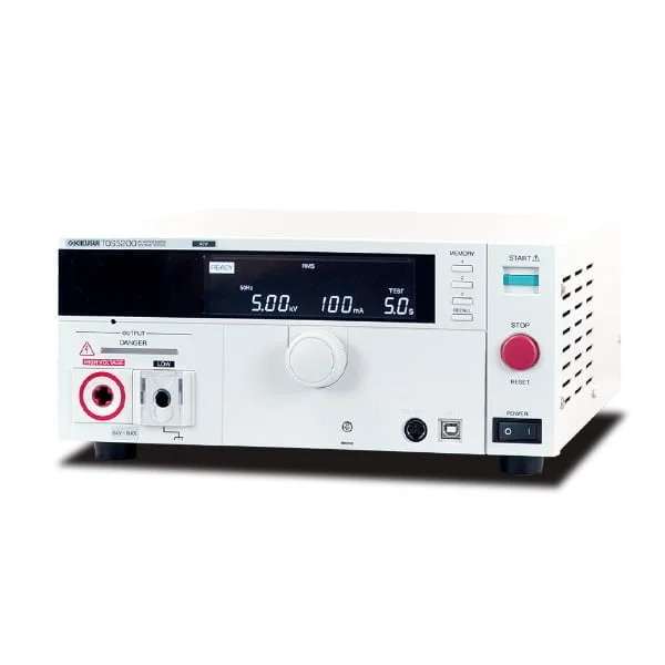
Withstanding voltage tester |
|||||||||||||||||||||||
|
format |
TOS5300 |
TOS5301 |
||||||||||||||||||||||
|
Basic function |
AC Withstanding Voltage Tester (ACW) |
AC/DC Withstanding Voltage Tester (ACW/DCW) |
||||||||||||||||||||||
|
■ Withstand voltage test section |
||||||||||||||||||||||||
|
AC |
output |
range |
0.05kV to 5.00kV |
|||||||||||||||||||||
|
Setting accuracy |
± (2 % of set + 20 V) [at no load] |
|||||||||||||||||||||||
|
Setting range |
0.00kV to 5.50kV |
|||||||||||||||||||||||
|
Setting resolution |
10V STEP |
|||||||||||||||||||||||
|
Maximum rated output |
500VA (5kV/100mA) |
|||||||||||||||||||||||
|
Maximum rated voltage |
5 kV |
|||||||||||||||||||||||
|
Maximum rated current |
100 mA [output voltage 0.5 kV or more] |
|||||||||||||||||||||||
|
transformer capacity |
500 VA |
|||||||||||||||||||||||
|
Output voltage waveform |
sine wave |
|||||||||||||||||||||||
|
Output voltage waveform Distortion factor |
Output voltage 0.5 kV or more: 3 % or less (at no load and pure resistance load) |
|||||||||||||||||||||||
|
frequency |
50Hz / 60Hz |
|||||||||||||||||||||||
|
Frequency accuracy |
±0.5 % (except during voltage rise) |
|||||||||||||||||||||||
|
voltage regulation |
10% or less (maximum rated load → no load) |
|||||||||||||||||||||||
|
Input voltage fluctuation |
± 0.3 % (at 5 kV no load, supply voltage 90 V to 250 V) |
|||||||||||||||||||||||
|
Short-circuit current |
200 mA or more (output voltage 1.0 kV or more) |
|||||||||||||||||||||||
|
Output method |
PWM switching method |
|||||||||||||||||||||||
|
DC |
output |
range |
− |
0.05kV to 6.00kV |
||||||||||||||||||||
|
Setting accuracy |
± (2 % of set + 20 V) |
|||||||||||||||||||||||
|
Setting range |
0.00kV to 6.20kV |
|||||||||||||||||||||||
|
Setting resolution |
10V STEP |
|||||||||||||||||||||||
|
Maximum rated output |
|
50W (5kV/10mA) |
||||||||||||||||||||||
|
Maximum rated voltage |
6 kV |
|||||||||||||||||||||||
|
Maximum rated current |
10mA |
|||||||||||||||||||||||
|
Ripple |
5 kV |
50 Vp-p |
||||||||||||||||||||||
|
Maximum rated |
100 Vp-p |
|||||||||||||||||||||||
|
voltage regulation |
3% or less (maximum rated load → no load) |
|||||||||||||||||||||||
|
Short circuit current (TYP value) |
40 mA (at 6 kV output) |
|||||||||||||||||||||||
|
discharge function |
Forced discharge at the end of the test (discharge resistance 125 kΩ) |
|||||||||||||||||||||||
|
Start Voltage |
The voltage at the start of the withstanding voltage test can be set to 50% of the set voltage |
|||||||||||||||||||||||
|
Limit Voltage |
Upper limit reference value for test voltage setting can be set |
|||||||||||||||||||||||
|
Output voltage monitoring function |
When the output voltage exceeds the set value (±350V), the output is cut off for protection. |
|||||||||||||||||||||||
|
voltmeter |
analog |
scale |
6kV AC/DC fs |
|||||||||||||||||||||
|
Accuracy |
±5% fs |
|||||||||||||||||||||||
|
instructions |
Average response/rms scale |
|||||||||||||||||||||||
|
Digital |
Measurement range |
0.000kV to 6.500kV AC/DC |
||||||||||||||||||||||
|
display |
□ . □□□ kV |
|||||||||||||||||||||||
|
Accuracy |
V < 500V: ± (1.5% of rdng + 20V) |
|||||||||||||||||||||||
|
response |
True rms/average response rms display switchable |
|||||||||||||||||||||||
|
Hold |
Holds the measured voltage value at the end of the test during the PASS/FAIL period. |
|||||||||||||||||||||||
|
Ammeter |
Digital |
Measurement range |
AC: 0.00mA to 110mA |
AC: 0.00mA to 110mA |
||||||||||||||||||||
|
display |
i = measured current |
|||||||||||||||||||||||
|
Accuracy |
1.00 mA ≤ i: ± (1.5 % of rdng) |
|||||||||||||||||||||||
|
response |
True rms/average response rms display switchable |
|||||||||||||||||||||||
|
Hold |
Holds the measured voltage value at the end of the test during the PASS period |
|||||||||||||||||||||||
|
Judgment |
Judgment method/judgment action |
· PASS signal is output continuously until STOP is input when PASS HOLD is set · UPPER FAIL and LOWER FAIL signals are output continuously until STOP is input · Adjustable FAIL or PASS buzzer volume · The buzzer sound at PASS judgment is fixed at 0.2 s, and the buzzer is turned off at 0.2 s even during PASS HOLD. |
||||||||||||||||||||||
|
Upper limit reference value setting |
AC: 0.01mA to 110mA |
AC: 0.01mA to 110mA |
||||||||||||||||||||||
|
Lower reference value setting |
AC: 0.01mA to 110mA/OFF |
AC: 0.01mA to 110mA/OFF |
||||||||||||||||||||||
|
Judgment accuracy |
1.00 mA ≤ i: ± (1.5 % of set) |
|||||||||||||||||||||||
|
Current detection method |
Calculate the true rms value of the current or the average value and compare it with the reference value |
|||||||||||||||||||||||
|
Proofreading |
Calibrated at the rms value of a sine wave with a purely resistive load |
|||||||||||||||||||||||
|
time |
Voltage Rise |
range |
0.1s to 10.0s |
|||||||||||||||||||||
|
Setting resolution |
0.1s |
|||||||||||||||||||||||
|
Voltage fall time |
0.1 s / OFF (valid only for PASS judgment) |
|||||||||||||||||||||||
|
Test |
range |
0.1 s to 999 s test time off (TIMER OFF) function available |
||||||||||||||||||||||
|
Setting resolution |
0.1s to 99.9s: 0.1s / 100s to 999s: 1s |
|||||||||||||||||||||||
|
Accuracy |
± (100 ppm + 20 ms) |
|||||||||||||||||||||||
|
■ Other functions/interfaces |
||||||||||||||||||||||||
|
Double Action |
The test starts only when the START switch is pressed within 0.5 seconds after the STOP switch is pressed and released. |
|||||||||||||||||||||||
|
PASS judgment holding time (Pass Hold) |
Set time to hold PASS judgment: 50 ms/ 100 ms/ 200 ms/ 1 s/ 2 s/ 5 s/ HOLD |
|||||||||||||||||||||||
|
Momentary function (Momentary) |
Run the test only while the START switch is pressed |
|||||||||||||||||||||||
|
Fail mode function |
Disable FAIL or PROTECTION release by remote control stop signal |
|||||||||||||||||||||||
|
Timer function (TIMER) |
End the test after the set time has passed |
|||||||||||||||||||||||
|
Output voltage monitoring function (Volt Error) |
When the output voltage exceeds ±350 V of the set value, |
|||||||||||||||||||||||
|
Memory |
Memorize up to 3 test conditions |
|||||||||||||||||||||||
|
Key lock |
Disabling only setting/change operations from the panel |
|||||||||||||||||||||||
|
protection |
In the following conditions, it shifts to the PROTECTION state, immediately cuts off the output, and stops the test. Show message on screen |
|||||||||||||||||||||||
|
Interlock protection |
When an interlock signal input is detected |
|||||||||||||||||||||||
|
Power supply protection |
When an abnormality in the power supply is detected |
|||||||||||||||||||||||
|
Volt Error Protection |
When the output voltage is monitored and a voltage exceeding the specified range is detected, |
|||||||||||||||||||||||
|
Over load protection |
If the power is set to the output limit power or more during the withstand voltage test, |
|||||||||||||||||||||||
|
Over heat protection |
When the temperature inside the product rises abnormally |
|||||||||||||||||||||||
|
Over Rating Protection |
When the output current exceeds the specified time during the withstand voltage test |
|||||||||||||||||||||||
|
Calibration protection |
When the set calibration deadline has passed |
|||||||||||||||||||||||
|
Remote protection |
When the disconnection of the REMOTE connector on the front panel is detected |
|||||||||||||||||||||||
|
SIGNAL I/O Protection |
When the ENABLE signal of the SIGNAL I/O connector on the rear panel changes |
|||||||||||||||||||||||
|
USB protection |
When the USB connector is pulled out during control with the USB interface |
|||||||||||||||||||||||
|
system clock |
display |
Year/Month/Day Hour:Minute:Second |
||||||||||||||||||||||
|
Date and time of calibration |
Set during calibration service |
|||||||||||||||||||||||
|
Calibration Due Control |
Set next calibration due date |
|||||||||||||||||||||||
|
Calibration Expired Warning (Calibration Protection) |
Set the operation when the set calibration deadline has passed. Display a warning when the power is turned on, or switch to a protection state to disable testing |
|||||||||||||||||||||||
|
interface |
USB |
USB Specification 2.0 |
||||||||||||||||||||||
|
REMOTE |
Front panel 9-pin MINI DIN connector Allows connection of options for remote start/stop control |
|||||||||||||||||||||||
|
SIGNAL I/O |
Rear panel D-sub 25 pin connector |
|||||||||||||||||||||||
|
■ General specifications |
||||||||||||||||||||||||
|
display |
VFD: 256 x 64 dots + 4 STATUS display |
|||||||||||||||||||||||
|
Backup battery life |
3 years (at 25°C) |
|||||||||||||||||||||||
|
environment |
Installation location |
Indoors, up to 2000 m altitude |
||||||||||||||||||||||
|
Specification guarantee range temperature/humidity |
5°C to 35°C / 20% rh to 80% rh (non-condensing) |
|||||||||||||||||||||||
|
Operating range temperature/humidity |
0°C to 40°C / 20% RH to 80% RH (non-condensing) |
|||||||||||||||||||||||
|
Storage range temperature/humidity |
-20°C to 70°C/90% rh or less (no condensation) |
|||||||||||||||||||||||
|
power supply |
Nominal voltage range (allowable voltage range) |
100Vac to 240Vac (90Vac to 250Vac) |
||||||||||||||||||||||
|
power consumption |
No load |
100 VA or less |
||||||||||||||||||||||
|
at rated load |
Up to 800VA |
|||||||||||||||||||||||
|
Allowable frequency range |
47Hz to 63Hz |
|||||||||||||||||||||||
|
Insulation resistance (between AC LINE and chassis) |
30 MΩ or more (500 Vdc) |
|||||||||||||||||||||||
|
Dielectric strength (between AC LINE and chassis) |
1400 Vac, 2 seconds (100% test) / 1500 Vac, 1 minute (type test) |
|||||||||||||||||||||||
|
ground continuity |
25Aac/0.1Ω or less |
|||||||||||||||||||||||
|
safety |
Conforms to the requirements of the following directives and standards |
|||||||||||||||||||||||
|
Electromagnetic Compatibility (EMC) |
Conforms to the requirements of the following directives and standards: |
|||||||||||||||||||||||
|
External dimensions (maximum size) |
320 (330) W x 132 (150) H x 350 (420) D mm |
|||||||||||||||||||||||
|
mass |
about 14kg |
about 15kg |
||||||||||||||||||||||
|
accessories |
1 power cord 1 set of high voltage test leads ( TL31 -TOS) ( 1 |
|||||||||||||||||||||||


") Realtools Asia(ศูนย์รวมเครื่องมือวัดและชุดทดสอบอุตสาหกรรม)
Realtools Asia(ศูนย์รวมเครื่องมือวัดและชุดทดสอบอุตสาหกรรม)
